Spot: 3D-printed Robot Dog
I came across this project online, and I was excited to find something affordable and relatively simple for someone who is new to robotics. I figured this would be a great foundation to understanding and implementing controls, gaits, and other features such as speech or facial recognition. My friend Reed and I committed a few weekends to creating this robot, and we are now learning how to program Spot to walk.
Getting Started
We decided to use the design from the Instructables website because this was our first robot, and it was important to understand proper design choices. For example, dual servo links provide structural stability, and the compact nature of the legs allows for maximum torque. As an electrical engineer, I learned a lot about robot mechanics and design.
The tutorial included STL files for 3D printing. However, the robot is designed to use 8x19x7mm ball bearings and have a laser cut acrylic sheet. Because we wanted a fully 3D printed dog, the ball bearings at that size were quite expensive, and the tutorial only provided the STL files, we decided to recreate the design in Autodesk Fusion 360 to have more control over parts and future changes.

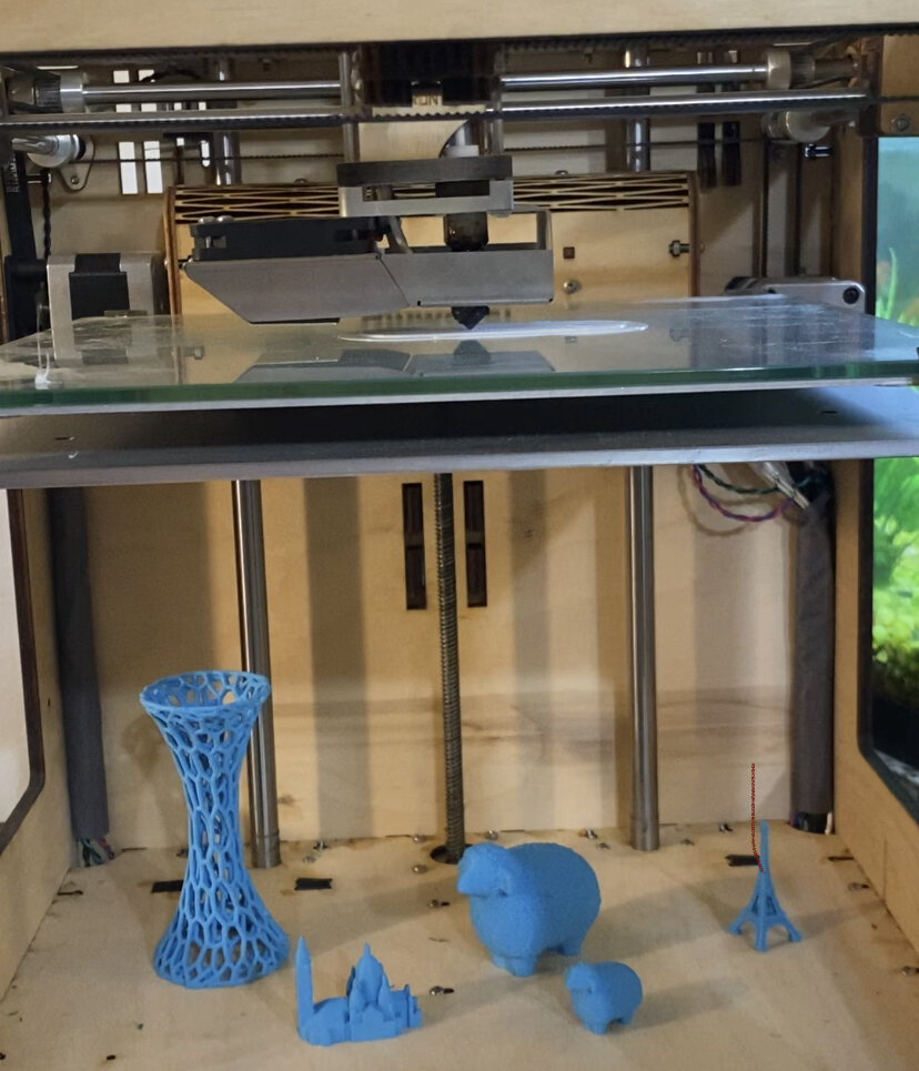
3D printing
Spot was printed in PLA and Amphora, which has the strength of ABS and the safety of PLA. I have an Ultimaker Original +, and Reed has an Anet A8. It was a challenge getting the first few layers on my printer looking decent. I believe the glass bed creates a lot of edge curling. Even when using masking tape on the bed, I was still having heating issues. Additionally, the speed on the first layer of the body was extremely slow to be able to print the screw holes successfully.

The biggest challenge to assembling Spot was removing the support debris from the printed parts. Reed’s printer created supports for the knee and elbow brackets, and they were surprisingly stuck to the part.
I also painted Spot because the printed base looked a little rough.

Recreating Spot in CAD
Reed added most of the parts and also taught me how to use Autodesk Fusion 360. We changed the ball bearings to 8x22x7mm, created the base with four supports printed directly to the base, and made Spot’s body slightly smaller so it could be 3D printed on an 8x8x8 in. printer. Additionally, we changed how the legs were assembled in order to be able to screw the elbow servo horns to the servo.
Assembly pictures

All put together
Spot is put together. The servos are initialized to a resting position. When we tried the provided walking gait, his feet kept slipping, so we’ve sprayed liquid rubber on his feet to hopefully provide more friction.
Walking- Current State of Spot
The code from the Instructables used inverse kinematics to explicitly calculated the servo angles when given a position. This is not very accurate for bigger movements, and the walking gait implies two arms, not three.
I would like to try to implement a fuzzy solution for more complex systems. I am first trying to implement this in MATLAB before applying it to Spot.
EEG Brain Wave Circuit
Another project that I’ve been working on is a real time EEG Brain Wave reader and processor. In the future, I would like to connect this project to Spot, such as having Spot walk over to comfort someone if their anxiety levels are higher than normal. I found an inexpensive EEG circuit design on Instructables. This circuit has three electrodes. I thought it would be a good introduction into learning about biosignals and real time processing.
Analog Circuit
For the analog circuit, I used the design found in the Instructables. This involves creating a circuit with an instrumentation amplifier to take in the voltage differences across the scalp, and various filters to focus on the EEG frequencies and filter out 60Hz interference. Specifically, the circuit has two 60Hz notch filters, a two pole 7 Hz high pass filter, a two pole 31 Hz low pass filter, and an extra high pass filter for controlling the gain.
Digital Design
Where I wanted to be creative was in the digital processing of this. For adaptability, real time processing, parallel ability, and large I/O compatibility, I wanted to try this project using an FPGA to process the real time data. It’s kind of overkill for one signal, but it’s a good project to better understand FPGAs, real time processing, and versatility in design. In the future, I’d like to be able to input and process multiple signals simultaneously to understand more complex emotions.
I’m using a DE10 Nano FPGA from Terasic. I chose this because of the extensive documentation (for FPGAs) and it’s relatively low cost. Currently, I’m learning how to use Quartus (instead of Vivado) to program FPGAs.

Current Status
I’m waiting for the DE10 Nano to arrive. In the meantime, I’m testing the output voltage to ensure the voltage doesn’t exceed 1V before plugging it in to my computer via a 3mm audio cable.